We use cookles to Improve your online experience. By continuing browsing this website, we assume you agree our use of cookies.

Quality Control in Rigid PCB Manufacturing: Ensuring High-Performance Boards
September 3rd, 2025
212 views
Quality Control in Rigid PCB Manufacturing: Ensuring High-Performance Boards
Rigid PCBs are the foundational components of nearly every electronic device—from consumer smartphones to automotive ADAS and medical implants. Their performance directly impacts the reliability, safety, and lifespan of end products. In PCB Manufacturing, quality control (QC) is not a standalone step but a systematic, end-to-end process that begins with raw material selection and continues through every stage of production, final testing, and even post-delivery support. Poor QC can lead to catastrophic failures: a single faulty via in an automotive BMS PCB could cause battery overheating, while a trace defect in a medical device PCB might compromise patient safety.
ShwayPCB’s PCB manufacturing services prioritize rigorous QC aligned with global standards (IPC, ISO, IATF) to deliver rigid PCBs with 99.5% first-pass yield (FPY) and consistent high performance. This guide breaks down the critical QC stages in rigid PCB manufacturing, explains technical methodologies, and highlights how proactive quality measures prevent defects and ensure long-term reliability.
1. Foundational QC: Incoming Material Inspection (IQC)
The quality of a rigid PCB starts with the quality of its raw materials. Incoming Material Inspection (IQC) is the first line of defense against defects, verifying that substrates, copper foils, prepreg, and surface finishes meet specifications before production begins.
Key IQC Processes for Critical Materials
- FR4 Substrate Inspection:
- Tg (Glass Transition Temperature) Testing: Using differential scanning calorimetry (DSC) to confirm Tg aligns with project requirements (e.g., 170°C for automotive, 200°C for aerospace). Deviations of ±5°C can cause warpage during lamination.
- Dielectric Strength & Loss: Measuring dielectric strength (≥40 kV/mm per IPC-4101) to ensure insulation between layers, and dielectric loss (Df ≤0.02 at 1 GHz for high-frequency designs) to prevent signal degradation.
- Copper Adhesion: Conducting peel strength tests (≥1.5 N/mm for 1oz copper) to ensure copper foil does not delaminate during etching or thermal cycling.
- Prepreg & Solder Paste Inspection:
- Resin Content & Flow: Verifying prepreg resin content (50–60% for standard FR4) and flow characteristics (20–30% flow during lamination) to avoid voids between layers.
- Solder Paste Alloy & Particle Size: For SMT assembly, confirming solder paste alloy (e.g., SAC 305 for RoHS compliance) and particle size (Type 4: 20–38μm for fine-pitch components) to ensure uniform deposition.
Why IQC Matters
Skipping IQC risks using substandard materials that cause downstream failures. For example, ShwayPCB once rejected a batch of FR4 substrate with Tg 10°C below the specified 180°C—preventing potential warpage in 5,000 automotive rigid PCBs and avoiding a $100k rework cost. This stage is particularly critical for High-Tg Rigid PCB Manufacturing, where thermal stability is non-negotiable.
2. In-Process QC: Catching Defects During Production
In-process QC monitors each manufacturing stage to identify and correct defects before they propagate. This proactive approach is far more cost-effective than fixing defects post-production (rework costs increase 10x–100x once a PCB is fully assembled).
Critical In-Process QC Stages
- Circuit Pattern Transfer & Etching:
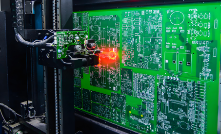
- Trace Width & Spacing Verification: Using optical comparators or laser scanners to measure trace dimensions (±0.01mm tolerance for IPC Class 3). For fine-pitch designs (≤0.1mm traces), automated optical inspection (AOI) with 5MP cameras detects over-etching (trace narrowing) or under-etching (residual copper).
- Etch Uniformity: Checking etch rate across the panel (variation ≤5%) to ensure consistent trace thickness. Uneven etching can create weak points that fail under current load.
- Drilling & Plating:
- Via Diameter & Placement: Using coordinate measuring machines (CMMs) to verify via diameter (±0.02mm) and placement accuracy (±0.005mm for laser-drilled microvias). Misaligned vias cause open circuits or short circuits between layers.
- Plating Thickness & Void Detection: Measuring copper plating thickness (18–25μm for signal layers) with X-ray fluorescence (XRF) and using 3D X-ray to inspect via walls for voids (<1% void area per IPC-6012). Voids reduce current-carrying capacity and increase thermal resistance.
- Lamination (Multi-Layer PCBs):
- Layer Alignment: Using automated optical alignment (AOA) systems to ensure layer-to-layer registration (±0.01mm). Misalignment of ≥0.02mm can short adjacent signal layers.
- Void Detection: Conducting ultrasonic scanning post-lamination to detect air voids (<0.1mm diameter) between layers. Voids expand under thermal cycling, leading to delamination.
ShwayPCB’s In-Process QC Approach
We implement "stationary QC"—assigning dedicated inspectors to high-risk stages (etching, lamination) and using real-time data dashboards to track defect rates. For example, our AOI systems flag trace width deviations in <1 second, triggering immediate adjustments to the etching process. This approach has reduced in-process defects by 35% for Turnkey PCB Manufacturing projects.
3. Final QC: Validating Performance and Reliability
Final QC ensures fully assembled rigid PCBs meet electrical, mechanical, and environmental performance standards before delivery. This stage combines electrical testing, visual inspection, and reliability screening to confirm the PCB is ready for end-use.
Key Final QC Tests
- Electrical Testing:
- Continuity & Insulation Resistance: Using bed-of-nails fixtures (high-volume) or flying probe testers (low-volume/fine-pitch) to check for opens (≥1MΩ) and shorts (≤100Ω). Insulation resistance testing (≥100MΩ at 500V DC) verifies no leakage between traces.
- Controlled Impedance Testing: For high-frequency designs (e.g., 5G, radar), using time-domain reflectometry (TDR) to measure impedance (±5% tolerance for 50Ω/75Ω traces). Impedance mismatches cause signal reflections and loss.
- Environmental & Mechanical Reliability Testing:
- Thermal Cycling: Exposing PCBs to -40°C to +125°C (1,000 cycles for automotive) to simulate in-field temperature changes. This tests solder joint integrity and layer adhesion—critical for Automotive PCB Manufacturing.
- Humidity Testing: Subjecting PCBs to 85°C/85% RH (500 hours per IPC-6012) to detect moisture-induced failures (e.g., corrosion, delamination).
- Mechanical Shock & Vibration: For aerospace/industrial PCBs, conducting shock tests (100G, 0.5ms) and vibration tests (10–2,000 Hz) to ensure structural stability.
- Visual Inspection:
- Surface Finish Quality: Checking ENIG finishes for gold thickness (≥0.1μm) and nickel corrosion, or HASL finishes for solder uniformity. Poor surface finishes cause solder joint failures during assembly.
- Component Placement (for Assembled PCBs): Verifying SMT component placement accuracy (±0.015mm) with 3D AOI to prevent tombstoning (component lifting) or solder bridging.
The Cost of Skipping Final QC
A consumer electronics client once requested to skip thermal cycling for 10,000 rigid PCBs to meet a tight deadline. ShwayPCB refused, and subsequent testing revealed 2% of boards had delaminated layers—avoiding a potential recall and $500k in warranty claims. Final QC is non-negotiable for regulated industries like medical (ISO 13485) and aerospace (MIL-STD-883H).
4. QC Standards: Aligning with Global Requirements
Rigid PCB QC must adhere to industry standards to ensure consistency and compliance. The most critical standards define defect acceptability, test methods, and performance criteria:
|
Standard
|
Focus Area
|
Key Requirements for Rigid PCBs
|
|
IPC-A-610
|
Electronic assembly acceptability
|
Class 1 (consumer): Minor defects allowed; Class 2 (industrial): Few defects; Class 3 (medical/aerospace): No critical defects.
|
|
IPC-6012
|
PCB performance specifications
|
dielectric strength, plating thickness, thermal cycling resistance, and void limits.
|
|
IATF 16949
|
Automotive-specific quality management
|
Mandatory for automotive PCBs; requires traceability (batch-level component tracking) and continuous improvement.
|
|
ISO 13485
|
Medical device quality management
|
Requires biocompatible materials (e.g., USP Class VI ENIG) and full documentation for regulatory submissions.
|
Why Standards Matter
Standards provide a common language for manufacturers and clients. For example, specifying "IPC Class 3" for a medical rigid PCB ensures ShwayPCB and the client agree on defect thresholds—avoiding miscommunication. Our AI-Driven PCB Manufacturing systems are programmed to flag deviations from these standards in real time, ensuring compliance at scale.
5. FAQ: Quality Control in Rigid PCB Manufacturing
1. What is the difference between IPC Class 2 and Class 3 QC standards?
- IPC Class 2 (industrial): Accepts minor defects (e.g., small solder balls <0.1mm, trace width deviations <10%) and is suitable for non-critical applications like home appliances.
- IPC Class 3 (medical/aerospace): Prohibits all critical defects (e.g., opens, shorts, via voids >1%) and requires stricter tolerances (trace width ±5%). Used for life-saving or mission-critical devices.
ShwayPCB defaults to Class 3 for Medical PCB Manufacturing and automotive safety-critical components.
2. How does AI enhance QC in rigid PCB manufacturing?
AI improves QC speed and accuracy by:
- AI-AOI: Learning from 100k+ defect images to detect subtle issues (e.g., micro-cracks, tiny solder bridges) that human inspectors miss—reducing false positives by 40%.
- Predictive QC: Analyzing in-process data (e.g., etch rate, drill bit wear) to predict defects before they occur. For example, our AI system alerts operators when drill bit sharpness degrades, preventing off-spec vias.
- Data Analytics: Tracking defect trends (e.g., 80% of etching defects occur on panel edges) to drive process improvements—reducing overall defect rates by 25% in 6 months.
3. Can QC detect counterfeit components in rigid PCB manufacturing?
Yes—through multi-step verification:
- Component Label Inspection: Checking for authentic logos, part numbers, and date codes (counterfeits often have blurry labels or incorrect markings).
- Dimensional Verification: Measuring component size (e.g., 01005 passives: 0.4mm × 0.2mm) with microscopes to spot oversized/undersized fakes.
- Supplier Traceability: Sourcing components only from authorized distributors (Avnet, Arrow) and requiring Certificate of Conformance (CoC) to confirm authenticity.
ShwayPCB rejects ~0.5% of components as counterfeit annually, preventing potential failures.
4. Is environmental testing (thermal cycling, humidity) necessary for all rigid PCBs?
It depends on the application:
- Consumer electronics (e.g., smartphones): Basic thermal cycling (500 cycles) suffices, as devices operate in controlled environments.
- Automotive/industrial: 1,000+ thermal cycles and humidity testing are mandatory to withstand extreme temperatures and moisture.
- Medical/aerospace: MIL-STD-883H shock/vibration testing plus long-term humidity exposure (1,000 hours) ensures reliability in harsh conditions.
ShwayPCB customizes environmental testing based on the end-use, balancing cost and risk.
5. How long does QC add to rigid PCB manufacturing lead times?
QC typically adds 1–3 days to lead times, but this is negligible compared to rework or recall costs:
- IQC: 4–8 hours for material testing.
- In-process QC: Integrated into production (no extra time for automated tests like AOI).
- Final QC: 1–2 days for electrical and environmental testing (expedited to 12 hours for urgent projects).
Our Turnkey PCB Manufacturing streamlines QC by aligning test schedules with production, minimizing delays.
6. Conclusion
Quality control in rigid PCB manufacturing is a holistic, data-driven process that ensures high performance, reliability, and compliance. From inspecting incoming FR4 substrates to conducting thermal cycling tests, every QC stage plays a critical role in preventing defects and protecting end users—whether in a consumer smartphone or a life-saving medical device. Cutting corners on QC may save time or money in the short term, but it leads to costly failures, recalls, and reputational damage.
ShwayPCB’s PCB manufacturing services embed QC into every stage of rigid PCB production, leveraging advanced tools (AI-AOI, 3D X-ray) and adherence to global standards (IPC, ISO, IATF) to deliver boards with 99.5% FPY. Our team works with clients to define custom QC plans aligned with their application’s unique needs—whether it’s a high-Tg automotive PCB or a miniaturized medical PCB with embedded components.
To discuss your rigid PCB’s QC requirements, request a copy of our quality manual, or get a customized quote for PCB Manufacturing, contact ShwayPCB at yuan@shwaypcb.com. For detailed specs on our testing equipment and compliance certifications, visit our dedicated PCB manufacturing services page.

Copyright © 2005-2025 ShwayPCB : PCB Fabrication and Assembly Manufacturer. All Rights Reserved. POWERED BY UEESHOP


Copyright © 2005-2025 ShwayPCB : PCB Fabrication and Assembly Manufacturer. All Rights Reserved. POWERED BY UEESHOP