We use cookles to Improve your online experience. By continuing browsing this website, we assume you agree our use of cookies.

PCB Box Build Assembly: Turning Individual PCBs into a Complete Functional Electronic System
September 3rd, 2025
167 views
PCB Box Build Assembly: Turning Individual PCBs into a Complete Functional Electronic System
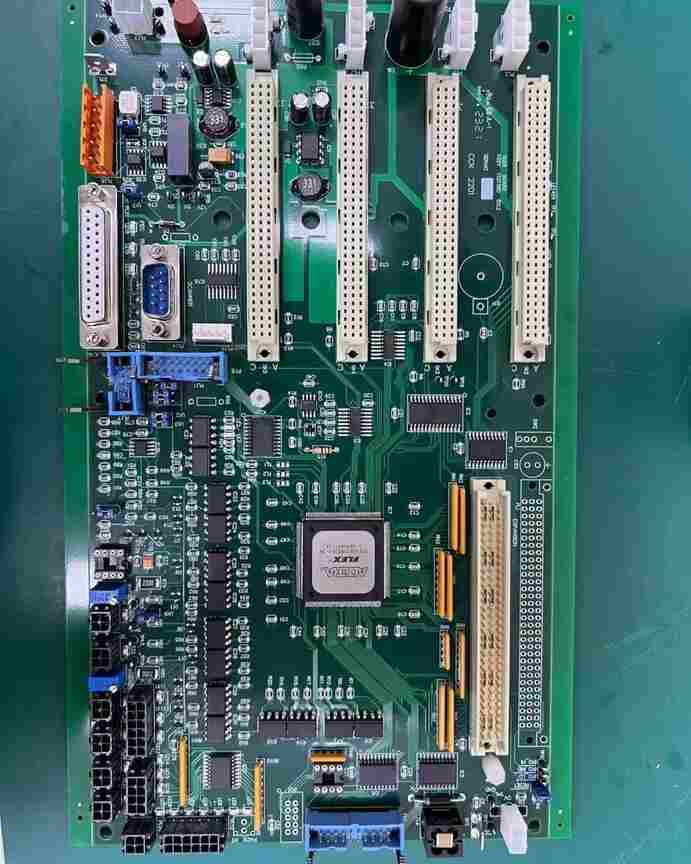
A printed circuit board (PCB) alone cannot deliver real-world value—most electronic systems require integration into a mechanical enclosure, paired with wiring, connectors, power supplies, and auxiliary components (e.g., fans, displays) to function as intended. PCB Box Build Assembly (also called "system integration") bridges this gap, transforming individual PCBs into fully operational, ready-to-deploy systems. From industrial control panels and automotive infotainment units to medical patient monitors, box build assembly ensures electronic components work in harmony with mechanical and environmental constraints—meeting performance, safety, and regulatory standards.
Unlike standalone PCB assembly, box build is a holistic process that combines electrical, mechanical, and software integration. This article explores the technical workflow of PCB box build assembly, key challenges (e.g., EMI shielding, thermal management), and how to ensure system-level reliability. It also highlights how ShwayPCB’s PCB Assembly Services specialize in box build integration, delivering turnkey systems that reduce time-to-market by 30% for clients across industries.
1. Core Workflow of PCB Box Build Assembly
PCB box build assembly follows a structured, sequential process to ensure seamless integration of electrical and mechanical components. Each step is validated to meet IPC-A-620 (standard for cable/wire harness assemblies) and application-specific standards (e.g., IEC 60950 for industrial enclosures).
1.1 Pre-Integration Preparation
Before physical assembly, two critical steps lay the groundwork for success:
- Bill of Materials (BOM) Validation:
- Cross-verify all components (PCBs, enclosures, wiring, connectors) against the BOM to ensure compatibility:
- PCB dimensions must fit enclosure cutouts (tolerance ±0.1mm for metal enclosures).
- Connector types (e.g., USB-C, MIL-DTL-38999) must match PCB pad layouts and enclosure port openings.
- Wire gauges (e.g., 22AWG for signal, 16AWG for power) must handle expected current (per IEC 60228) without overheating.
- For custom enclosures, validate material compatibility (e.g., ABS plastic for consumer devices, aluminum for industrial heat dissipation).
- Fixture and Tooling Setup:
- Fabricate custom mounting fixtures to secure PCBs during assembly (prevents bending or component damage).
- Prepare specialized tools: torque screwdrivers (for PCB mounting screws, torque range 0.5–2 N·m), wire strippers (precision ±0.1mm), and crimping tools (per IPC-A-620 for terminal crimps).
1.2 PCB and Component Mounting
The first physical step integrates PCBs into the mechanical enclosure, with strict attention to mechanical stability and thermal management:
- PCB Mounting:
- Use standoffs (nylon for insulation, metal for grounding) to secure PCBs to enclosure walls. Standoff height (typically 5–10mm) ensures airflow around the PCB (critical for heat dissipation in high-power systems).
- Torque mounting screws to specified values (e.g., 1.2 N·m for M3 screws) to avoid PCB warping (which can crack solder joints) or loose connections (which cause intermittent failures).
- Auxiliary Component Installation:
- Mount supporting components:
- Power Supplies: AC-DC converters (e.g., 12V/5A) must be secured with vibration-damping gaskets (for automotive or industrial use) to reduce noise transfer to PCBs.
- Cooling Systems: Fans or heat sinks are mounted near high-power PCBs (e.g., 10W microprocessors). Fan airflow direction is validated to ensure heat is exhausted outside the enclosure (per IEC 60584 for thermal performance).
- Displays/Sensors: Touchscreens or temperature sensors are aligned with enclosure windows (tolerance ±0.5mm) to ensure user accessibility or accurate readings.
1.3 Wiring and Harness Integration
Wiring is the "nervous system" of the box build—poorly executed harnesses cause 40% of box build failures (e.g., short circuits, signal loss). Key steps include:
- Wire Harness Fabrication:
- Cut wires to exact lengths (tolerance ±5mm) and strip insulation (exposing 2–3mm of conductor) per IPC-A-620.
- Crimp terminals (e.g., JST, Molex) with controlled force (20–30 N) to ensure electrical continuity (<0.01Ω resistance) and mechanical strength (>10N pull force).
- Organize harnesses with cable ties or sleeves (nylon for flexibility, Teflon for high temperatures) to avoid wire abrasion against enclosure edges.
- Interconnection to PCBs:
- Mate wire harnesses to PCB connectors with audible "clicks" (or torque locks for MIL-spec connectors) to confirm secure seating.
- Use strain reliefs (e.g., cable glands) for external wires (e.g., power cords, sensor cables) to prevent wire pull-out (per IEC 60335 for safety).
ShwayPCB’s Box Build Assembly Services use automated wire cutting/crimping machines for high-volume projects, achieving 99.8% harness accuracy vs. 95% for manual assembly.
1.4 Enclosure Sealing and Finishing
The final mechanical step prepares the system for deployment, with a focus on environmental protection and safety:
- Sealing:
- For outdoor or harsh-environment systems (IP65/IP67 ratings), apply gaskets (rubber or foam) between enclosure halves and seal cable entry points with O-rings. Pressure testing (50kPa for 10 minutes) verifies no water or dust ingress.
- For EMI-sensitive systems (e.g., medical imaging, aerospace), apply conductive gaskets (copper or nickel-coated foam) to enclosure seams—reducing EMI leakage by 40dB at 1GHz (per CISPR 22).
- Labeling and Documentation:
- Apply labels: serial numbers (for traceability), warning symbols (e.g., "high voltage"), and port identifiers (e.g., "Ethernet," "Power").
- Package documentation: user manuals, BOM copies, and test reports (thermal, electrical, environmental) for regulatory compliance.
1.5 System-Level Testing and Validation
Box build assembly concludes with rigorous testing to ensure the system functions as a unified unit:
- Electrical Testing:
- Continuity Testing: Verify all wire connections (no open circuits) and insulation resistance (>100MΩ at 500V DC) to prevent short circuits.
- Power-Up Testing: Apply rated voltage (e.g., 120V AC, 24V DC) and monitor for overcurrent (using inline fuses) or voltage drops (>5% is unacceptable for power rails).
- Functional Testing (FCT): Simulate real-world operation (e.g., industrial control panel: send/receive sensor data; medical monitor: display ECG signals) to validate end-to-end performance.
- Environmental Testing:
- Thermal Testing: Use infrared thermography to map enclosure temperatures—ensure no component exceeds maximum operating temperature (e.g., 85°C for industrial ICs).
- Vibration Testing: For automotive/industrial systems, subject the box build to 10–20G vibration (per ISO 16750-3) for 1 hour—no loose connections or component damage allowed.
2. Key Challenges of PCB Box Build Assembly
Box build integration introduces unique challenges that standalone PCB assembly does not—each requiring specialized solutions:
2.1 EMI/EMC Compliance
Electronic systems emit electromagnetic interference (EMI) that can disrupt nearby devices (e.g., medical monitors near MRI machines). Conversely, external EMI (e.g., factory motors) can corrupt PCB signals. Solutions include:
- Shielding: Use aluminum or steel enclosures (instead of plastic) and conductive gaskets to block EMI. For sensitive PCBs, add internal shielding cans (titanium or copper) around high-frequency components (e.g., 5G modules).
- Grounding: Implement a single-point grounding system—connect PCB ground planes, enclosure, and wire shields to a common ground point. This reduces ground loops (a major source of EMI) by 60%.
- Filtering: Install EMI filters on power inputs and signal lines (e.g., USB, Ethernet) to attenuate noise—compliant with CISPR 25 (automotive) or IEC 60601-1-2 (medical).
2.2 Thermal Management
Enclosed systems trap heat, which degrades PCB performance and reduces component lifespan. Mitigation strategies:
- Airflow Optimization: Design enclosures with vents (or fans) to create cross-flow ventilation. For high-power systems (100W+), use heat pipes to transfer heat from PCBs to enclosure walls.
- Thermal Interface Materials (TIM): Apply TIM (thermal grease, pads) between PCBs and heat sinks—improving thermal conductivity by 300% vs. air gaps.
- Component Placement: During pre-integration, place high-heat components (e.g., power amplifiers) near enclosure vents or heat sinks—avoiding clustering that creates hotspots (>100°C).
2.3 Mechanical Compatibility and Vibration Resistance
Enclosure materials, PCB mounting, and wiring must withstand mechanical stress (vibration, shock) to avoid failures:
- Enclosure Material Selection:
- Consumer devices: ABS plastic (lightweight, low cost).
- Industrial/automotive: Aluminum (high strength, good heat dissipation).
- Aerospace: Titanium (high strength-to-weight ratio, corrosion resistance).
- Vibration-Damping Mounts: Use rubber or silicone mounts for PCBs and power supplies—reducing vibration transfer by 70% (per MIL-STD-883H).
- Wire Harness Protection: Secure harnesses with adhesive clips (not just cable ties) to prevent movement during vibration—avoids wire fatigue and connector disengagement.
3. Real-World Application: Box Build for Industrial Control Panels
To illustrate box build assembly in action, consider a 24V DC industrial control panel used in factory automation:
3.1 System Requirements
- Components: 2x SMT PCBs (0.4mm-pitch BGAs for PLC logic), 1x through-hole power distribution PCB, aluminum enclosure (IP65), 22AWG signal wires, 16AWG power wires, 4x fans, and 1x 24V/10A power supply.
- Standards: IEC 60950 (electrical safety), IPC-A-620 (wiring), IP65 (dust/water resistance).
- Performance: Operate at -20°C to +60°C, withstand 15G vibration, and support 100+ sensor inputs.
3.2 Box Build Execution
- Pre-Integration: Validated PCB dimensions (150mm×200mm) fit enclosure cutouts (150.1mm×200.1mm) and wire gauges match current requirements (16AWG for 10A power).
- Mounting: Secured PCBs with 8mm aluminum standoffs (torque 1.5 N·m) and mounted fans near power PCBs (airflow 50 CFM).
- Wiring: Fabricated 20 signal harnesses (22AWG, JST connectors) and 5 power harnesses (16AWG, MIL-DTL-26482 connectors), using adhesive clips to secure harnesses to enclosure walls.
- Sealing: Applied EPDM gaskets to enclosure seams and cable glands for power/signal entry—passed IP65 pressure testing.
- Testing:
- Electrical: Continuity test (all connections valid), power-up (24V ±5% with no overcurrent).
- Functional: Controlled 5 factory motors via PLC PCBs, with sensor data displayed correctly.
- Environmental: Thermal testing (max enclosure temp 55°C at 60°C ambient), vibration testing (15G for 1 hour with no failures).
3.3 Outcome
- Yield: 99.6% first-pass yield (1 failure due to a loose fan connector, resolved via rework).
- Reliability: 0 field failures in 2 years of operation (10k+ hours).
- Time-to-Market: 4 weeks from PCB assembly to box build completion (30% faster than client’s previous supplier).
4. FAQ: PCB Box Build Assembly
1. What is the difference between PCB assembly and box build assembly?
- PCB Assembly: Focuses on soldering components (SMT/through-hole) to individual PCBs—no mechanical integration.
- Box Build Assembly: Integrates PCBs into enclosures with wiring, power supplies, and auxiliary components (fans, displays) to create a complete, functional system.
ShwayPCB offers both PCB Assembly Services and turnkey box build, streamlining the transition from PCB to system.
2. Can box build assembly handle custom enclosures?
Yes—custom enclosures are common for box build:
- ShwayPCB partners with mechanical manufacturers to design enclosures (aluminum, plastic, titanium) tailored to your PCB dimensions and environmental needs (IP ratings, EMI shielding).
- Prototyping services (3D printing for plastic enclosures, CNC machining for metal) allow validation before full-scale production.
3. How do you ensure EMI compliance for box build systems?
We use a three-step approach:
- Design: Aluminum enclosures, conductive gaskets, and single-point grounding.
- Testing: Pre-compliance EMI testing (using a spectrum analyzer) to identify noise sources.
- Mitigation: Add EMI filters to power/signal lines or internal shielding cans for high-frequency PCBs.
This ensures compliance with CISPR 22 (industrial), CISPR 25 (automotive), and IEC 60601-1-2 (medical).
4. What is the lead time for PCB box build assembly?
Lead times depend on complexity and volume:
- Prototypes (1–5 units): 2–3 weeks (includes enclosure fabrication, PCB assembly, and testing).
- Production (100+ units): 4–6 weeks (amortizes tooling and setup costs).
ShwayPCB offers expedited 1-week prototype service for emergency projects (e.g., factory downtime replacements).
5. How does box build assembly support regulatory compliance (e.g., medical, aerospace)?
We integrate compliance into every step:
- Component Sourcing: Use FDA-registered suppliers for medical components, MIL-spec suppliers for aerospace.
- Testing: Conduct environmental (thermal, vibration) and safety (insulation resistance, overcurrent) testing per standards (ISO 13485 for medical, DO-254 for aerospace).
- Documentation: Provide full traceability (component lot numbers, test reports) and compliance certificates for audits.
5. Conclusion
PCB Box Build Assembly is the critical final step in transforming individual PCBs into valuable, ready-to-use electronic systems. By integrating electrical components with mechanical enclosures, wiring, and auxiliary parts—while addressing challenges like EMI, thermal management, and vibration—box build ensures systems meet performance, safety, and regulatory standards. For manufacturers, box build reduces time-to-market, minimizes supply chain complexity (one provider for PCB + system integration), and lowers the risk of field failures.
ShwayPCB’s PCB Assembly Services include end-to-end box build integration, with expertise in industrial, automotive, medical, and aerospace applications. Our IPC-A-620-certified technicians, automated wire harness tools, and rigorous testing protocols deliver turnkey systems that exceed client expectations. Whether you need a prototype control panel or 10k units of a medical device, we tailor box build processes to your unique requirements.
To discuss your PCB box build project, request a design review for enclosure/PCB compatibility, or get a customized quote for Turnkey Box Build Assembly, contact ShwayPCB at yuan@shwaypcb.com. For detailed case studies (e.g., aerospace box build with DO-254 compliance) and technical guides on box build best practices, visit our dedicated PCB Assembly Services page.

Copyright © 2005-2025 ShwayPCB : PCB Fabrication and Assembly Manufacturer. All Rights Reserved. POWERED BY UEESHOP


Copyright © 2005-2025 ShwayPCB : PCB Fabrication and Assembly Manufacturer. All Rights Reserved. POWERED BY UEESHOP