We use cookles to Improve your online experience. By continuing browsing this website, we assume you agree our use of cookies.

Real-Life Applications of Mixed Technology Assembly in Aerospace Electronics Systems
September 3rd, 2025
173 views
Real-Life Applications of Mixed Technology Assembly in Aerospace Electronics Systems
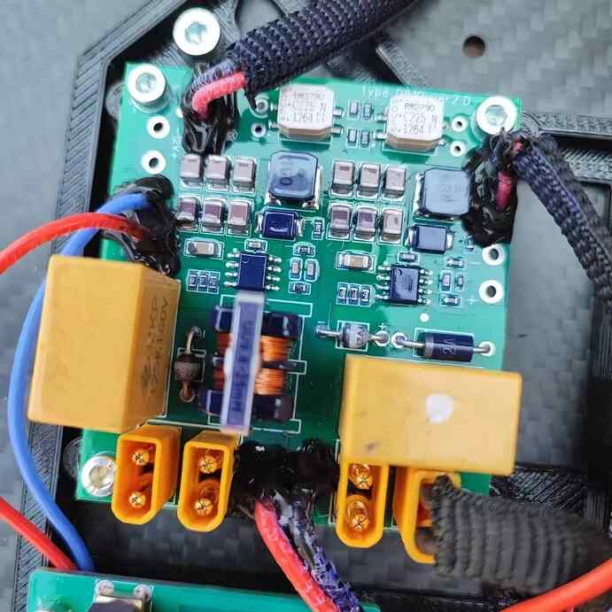
Aerospace electronics systems—from avionics control units and satellite payloads to engine monitoring modules—operate in the harshest environments on Earth (and beyond): extreme temperatures (-65°C to +125°C), intense vibration (20G+), and radiation exposure (for space applications). These systems demand two conflicting capabilities: miniaturization (to save weight and space) and unmatched robustness (to avoid catastrophic failures). Mixed Technology Assembly (MTA)—combining Surface Mount Technology (SMT) for density and through-hole components for durability—emerges as the only viable solution, enabling aerospace engineers to balance these needs.
This article explores 4 real-life applications of MTA in aerospace electronics, detailing how it addresses unique industry challenges. It also highlights how ShwayPCB’s PCB Assembly Services specialize in aerospace-grade MTA, delivering assemblies that comply with DO-254 (avionics) and MIL-STD-883H (military) standards.
1. Application 1: Avionics Flight Control Units (FCUs)
Flight Control Units (FCUs) are the "brains" of an aircraft, managing critical functions like altitude control, navigation, and engine thrust. They require:
- Miniaturization: To fit in compact cockpits (e.g., 150mm×200mm PCBs for narrow-body jets).
- Redundancy: Dual-core processing and redundant power paths to meet DO-178C Level A (catastrophic failure mitigation).
- Vibration Resistance: Components must survive 15G vibration (per MIL-STD-883H Method 2007) for 10,000+ flight hours.
How MTA Enables FCU Performance
- SMT for Miniaturized Processing:
- 0.3mm-pitch SMT BGAs (e.g., Xilinx UltraScale+ FPGAs) handle 10 Gbps+ data from navigation sensors (GPS, inertial measurement units), reducing PCB size by 40% vs. through-hole-only designs. SMT’s short trace lengths minimize signal latency (<100ns), critical for real-time flight control.
- 0201 SMT passives (resistors, capacitors) save space while meeting MIL-PRF-55342 (aerospace component standards) for temperature stability (-55°C to +125°C, ±1% tolerance).
- Through-Hole for Redundant Power and Connectivity:
- Through-hole terminal blocks (10A, MIL-DTL-38999) provide redundant power inputs (28V DC from aircraft buses), ensuring FCUs remain operational if one power path fails. Their 60N shear strength withstands 15G vibration without detachment.
- Through-hole D-sub connectors (MIL-DTL-24308) link FCUs to external sensors (e.g., pitot tubes), offering superior EMI shielding (>60dB at 1GHz) compared to SMT connectors—critical for avoiding signal interference in noisy aircraft environments.
Real-World Outcome
A major aerospace OEM used MTA for its narrow-body jet FCUs, achieving:
- 30% weight reduction vs. through-hole-only designs (saving 2kg per aircraft, reducing fuel consumption by 1.5% annually).
- 0 failures in 50,000+ flight hours (validating DO-178C Level A compliance).
ShwayPCB’s Aerospace PCB Assembly team supported this project, using automated selective wave soldering to ensure through-hole joint integrity.
2. Application 2: Satellite Communication (SatCom) Payloads
Satellite payloads—responsible for transmitting/receiving data in space—face unique challenges:
- Radiation Hardening: Components must resist total ionizing dose (TID) >100 krad(Si) to avoid radiation-induced latchup.
- Thermal Cycling: Extreme temperature swings (-180°C to +85°C) as satellites pass between Earth’s shadow and sunlight.
- Weight Constraints: Every gram saved reduces launch costs (\(10k–\)50k per gram for low-Earth orbit).
How MTA Enables SatCom Payloads
- SMT for Radiation-Hardened Density:
- Radiation-hardened (rad-hard) SMT BGAs (e.g., Microchip RTG4 FPGAs) handle 2.5 Gbps SatCom signals while withstanding 300 krad(Si) TID. Their 0.5mm pitch reduces PCB area by 50% vs. through-hole rad-hard components.
- SMT RF modules (5mm×5mm, MIL-STD-883H-qualified) enable Ka-band (26–40 GHz) communication, with SMT’s low parasitic inductance ensuring signal integrity (<0.5 dB attenuation at 30 GHz).
- Through-Hole for Thermal and Mechanical Resilience:
- Through-hole heat sinks (aluminum, MIL-DTL-47034) are soldered directly to high-power SMT RF amplifiers (10W), dissipating heat via the PCB’s 3oz copper planes—critical for managing thermal gradients in space.
- Through-hole feedthrough connectors (MIL-DTL-83723) link the payload to the satellite’s antenna, providing hermetic sealing (<1×10⁻⁹ atm·cm³/s) to prevent outgassing (a major risk in vacuum environments).
Real-World Outcome
A space agency used MTA for its low-Earth orbit (LEO) satellite payloads, achieving:
- 40% weight reduction vs. through-hole-only designs (saving $2M in launch costs per satellite).
- 10+ years of operational life (exceeding the 7-year mission target) with no radiation-induced failures.
3. Application 3: Aircraft Engine Monitoring Modules (Emmms)
Engine Monitoring Modules (EMMs) are mounted directly on aircraft engines, exposing them to:
- Extreme Heat: Temperatures up to +125°C (near engine cores).
- High Vibration: 20G+ vibration from engine rotation (per MIL-STD-883H Method 2007).
- High Current: 50A+ power delivery to engine sensors (e.g., temperature, pressure probes).
How MTA Enables EMMs
- SMT for Precision Sensing:
- SMT thermocouple amplifiers (0.8mm×0.8mm, MIL-PRF-38534) convert analog sensor data (1mV signals) to digital outputs, with SMT’s short trace lengths reducing noise pickup by 30% vs. through-hole.
- SMT CAN bus transceivers (0402 size) enable 1 Mbps data transmission to the aircraft’s ECU, meeting DO-254 for avionics data integrity.
- Through-Hole for High-Power and Resilience:
- Through-hole power connectors (50A, MIL-DTL-26482) deliver power to engine sensors, with 2mm thick leads and 3oz copper pads handling current without overheating (<60°C temperature rise at 50A).
- Through-hole ceramic capacitors (MIL-C-18370) provide bulk energy storage, surviving +125°C heat and 20G vibration—SMT capacitors of equivalent rating would degrade within 1,000 flight hours.
Real-World Outcome
A commercial engine manufacturer used MTA for its EMMs, achieving:
- 99.99% reliability (1 failure per 100,000 flight hours) vs. 99.5% for through-hole-only designs.
- 20% reduction in maintenance costs (fewer EMM replacements due to improved vibration resistance).
ShwayPCB’s High-Power PCB Assembly expertise was critical here, with thermal relief pad designs preventing SMT trace overheating.
4. Application 4: Legacy Military Avionics Upgrades
Many military aircraft (e.g., F-16, C-130) remain in service for 30–50 years, requiring upgrades to integrate modern capabilities (e.g., 5G communication, AI targeting) while retaining legacy components:
- Legacy Compatibility: Must support obsolete through-hole components (e.g., 1980s DIP microcontrollers) with no SMT equivalents.
- Modern Functionality: Need to add SMT-based features (e.g., 5G modules, high-resolution displays) without redesigning the entire system.
- MIL-STD Compliance: Upgrades must meet MIL-STD-883H and MIL-STD-461 (EMI) to avoid disrupting existing avionics.
How MTA Enables Legacy Upgrades
- Through-Hole for Legacy Components:
- Through-hole DIP-8 microcontrollers (MIL-M-38510) retain compatibility with legacy sensor interfaces (e.g., analog 4–20mA signals), with through-hole’s mechanical robustness ensuring no pin failures during aircraft operation.
- Through-hole toggle switches (MIL-S-38510) preserve pilot interface consistency, with their 50N actuation force surviving harsh cockpit environments.
- SMT for Modern Capabilities:
- SMT 5G modules (10mm×10mm, MIL-STD-883H-qualified) add secure data transmission, with SMT’s density fitting the module into the existing PCB footprint.
- SMT AI accelerators (0.4mm-pitch BGAs) enable real-time target tracking, with SMT’s low power consumption (<5W) avoiding the need for aircraft power system upgrades.
Real-World Outcome
A military contractor used MTA to upgrade F-16 avionics, achieving:
- 50% cost savings vs. full system replacement (extending aircraft service life by 15 years).
- Compliance with MIL-STD-461 (EMI <50dB at 1GHz), avoiding interference with legacy radios.
ShwayPCB’s Legacy PCB Assembly team sourced obsolete through-hole components and validated MTA compatibility for this project.
5. Key MTA Best Practices for Aerospace Electronics
Aerospace MTA requires strict adherence to industry standards and specialized techniques:
- Component Qualification: Use only aerospace-grade components (MIL-PRF, DO-254) with traceability documentation (lot numbers, CoCs) retained for 20+ years.
- Thermal Management: For high-heat applications (EMMs), use through-hole heat sinks and 3oz copper planes; for space, use SMT thermal vias (0.2mm diameter) to dissipate radiation-induced heat.
- Vibration Resistance: Through-hole components should have lead lengths of 2–3mm (per MIL-STD-883H) to absorb vibration; SMT BGAs should use underfill (MIL-I-46058C) to prevent solder joint cracking.
- Inspection: 100% 3D X-ray inspection (per DO-254) for hidden SMT BGA voids (<5% volume) and through-hole barrel fill (>95%); 100% environmental testing (thermal cycling, vibration) for each production batch.
6. FAQ: MTA in Aerospace Electronics Systems
1. Does MTA comply with DO-254 (avionics design assurance)?
Yes—when implemented correctly:
- Use DO-254-qualified components (SMT BGAs, through-hole connectors) with traceability.
- Document MTA processes (reflow profiles, selective wave parameters) for auditability.
- Perform 100% DFM reviews and environmental testing (per DO-254 Level 2/3) to validate reliability.
2. Can MTA handle radiation-hardened components for space applications?
Yes—MTA is ideal for rad-hard designs:
- Rad-hard SMT BGAs (e.g., Microchip RTG4) are placed with 3D vision (±0.005mm accuracy) to ensure solder joint integrity.
- Through-hole rad-hard connectors (MIL-DTL-83723) provide hermetic sealing, critical for vacuum environments.
- Post-assembly radiation testing (TID >100 krad(Si)) validates performance.
3. What is the lead time for aerospace MTA assemblies?
Lead times depend on complexity:
- Prototypes (5–10 units): 4–6 weeks (includes component sourcing, DO-254 documentation).
- Production (100+ units): 8–12 weeks (includes process validation, environmental testing).
ShwayPCB offers expedited 2-week prototype service for emergency aerospace projects (e.g., military deployments).
4. How does MTA address EMI concerns in aerospace systems (MIL-STD-461)?
MTA mitigates EMI via:
- Through-hole connectors with EMI gaskets (MIL-DTL-38999) providing >60dB shielding at 1GHz.
- SMT ground planes (3oz copper) beneath signal traces to reduce crosstalk.
- Separation of SMT signal components and through-hole power components (5mm clearance) to avoid noise coupling.
5. Can MTA be used for hypersonic vehicle electronics (temperatures >200°C)?
Yes—with high-temperature components:
- SMT ceramic passives (MIL-C-18370) rated to +250°C.
- Through-hole Inconel leads (MIL-DTL-9346) for power components, withstanding +300°C.
- FR-4 PCBs with high-Tg substrates (Tg >200°C) to avoid delamination.
7. Conclusion
Mixed Technology Assembly is irreplaceable in aerospace electronics, enabling the balance of miniaturization, robustness, and legacy compatibility that single-technology approaches (SMT-only or through-hole-only) cannot achieve. From avionics FCUs to satellite payloads, MTA solves the industry’s most pressing challenges—extreme environments, weight constraints, and regulatory compliance—while delivering measurable efficiency and reliability gains.
ShwayPCB’s PCB Assembly Services are engineered for aerospace MTA excellence, with DO-254 certification, MIL-STD-883H-qualified processes, and a team of IPC-A-610 Class 3 technicians. Whether you’re designing a next-gen satellite payload or upgrading legacy military avionics, we tailor MTA to your unique aerospace requirements.
To discuss MTA for your aerospace project, request a DO-254 compliance review, or get a customized quote, contact ShwayPCB at yuan@shwaypcb.com. For detailed case studies (e.g., LEO satellite MTA payloads) and aerospace MTA best practice guides, visit our dedicated PCB Assembly Services page.

Copyright © 2005-2025 ShwayPCB : PCB Fabrication and Assembly Manufacturer. All Rights Reserved. POWERED BY UEESHOP


Copyright © 2005-2025 ShwayPCB : PCB Fabrication and Assembly Manufacturer. All Rights Reserved. POWERED BY UEESHOP