We use cookles to Improve your online experience. By continuing browsing this website, we assume you agree our use of cookies.

How to Select a Mixed Technology Assembly Service That Can Handle Your Diverse Component Needs
September 3rd, 2025
136 views
How to Select a Mixed Technology Assembly Service That Can Handle Your Diverse Component Needs
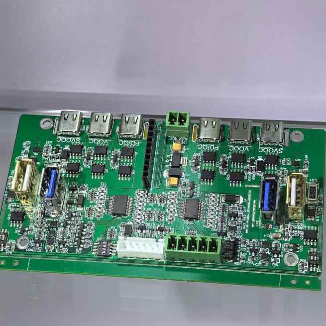
Mixed Technology Assembly (MTA)—combining Surface Mount Technology (SMT) and through-hole components—demands a service provider with the flexibility to handle wildly diverse parts: from 01005 SMT passives (0.4mm×0.2mm) to 50g through-hole transformers, and from 0.3mm-pitch BGAs (for high-speed signals) to 20A terminal blocks (for power delivery). Choosing a provider ill-equipped for this diversity leads to 30–40% yield losses, missed deadlines, and costly rework—especially for complex electronics like industrial PLCs, automotive ECUs, or medical imaging devices.
Selecting the right MTA service requires more than evaluating basic assembly capabilities; it means validating a provider’s technical expertise in component-specific processing, process integration, and quality control. This article outlines a structured, technical approach to choosing an MTA service that meets your diverse component needs, from SMT miniaturization to through-hole robustness. It also highlights how ShwayPCB’s PCB Assembly Services are engineered for component diversity, delivering 99.5% first-pass yields for clients with mixed SMT/through-hole requirements.
1. Step 1: Validate Component Compatibility—Ensure They Handle Your Specific Part Mix
The first critical check is confirming the provider can process your exact component types—not just generic SMT/through-hole parts. Diverse MTA needs require validation across three categories:
1.1 SMT Component Capabilities
Your provider must handle the full range of SMT parts in your design, including:
- Fine-Pitch and Miniaturized Parts:
- Verify ability to assemble 01005 passives (smallest standard SMT size) and 0.3mm-pitch BGAs (common in high-speed electronics). Ask for:
- Placement accuracy data (target: ±0.005mm for 0.3mm-pitch BGAs).
- First-pass yield rates for fine-pitch assemblies (e.g., 99.7% for 0.4mm-pitch BGAs).
- Red Flag: Providers using 2D-only vision systems struggle with 0.3mm-pitch BGAs—insist on 3D vision placement machines (e.g., Universal Instruments FuzionXC).
- High-Speed and Specialized SMT Parts:
- For RF components (e.g., 5G mmWave modules) or thermal-sensitive parts (e.g., plastic-encapsulated BGAs), confirm:
- Use of nitrogen-enriched reflow (O₂ <100 ppm) to prevent oxidation and thermal damage.
- Signal integrity testing capabilities (e.g., BERT for 10 Gbps+ BGAs).
1.2 Through-Hole Component Capabilities
Through-hole diversity often includes odd-form, high-power, or legacy parts—validate these specific capabilities:
- Odd-Form and Heavy Components:
- For parts like 50g transformers, custom terminal blocks, or large connectors, ask:
- Maximum component weight capacity (target: ≥100g for automated insertion; manual handling protocols for heavier parts).
- Use of heat sinks during hand soldering to protect adjacent SMT components (critical for parts requiring 350–380°C soldering temperatures).
- High-Power and Legacy Parts:
- For 20A+ through-hole connectors or obsolete DIP microcontrollers (common in legacy industrial gear), confirm:
- Thick-copper PCB processing (2–3oz copper pads) to handle high currents without overheating.
- Legacy component sourcing partnerships (e.g., with Digi-Key Military or Arrow Defense) to avoid counterfeits.
ShwayPCB’s Hybrid PCB Assembly handles this full spectrum—from 01005 SMT passives to 100g through-hole transformers—with specialized tools for each component type.
2. Step 2: Evaluate Process Flexibility—Ensure Integration of SMT and Through-Hole
MTA’s greatest challenge is integrating two distinct processes without compromising either. A capable provider must demonstrate flexibility in three key process areas:
2.1 Sequential Processing Optimization
The optimal MTA workflow (SMT first, then through-hole) is non-negotiable—but providers must adapt it to your component mix:
- SMT-to-Through-Hole Transition:
- Ask for documentation of how they protect SMT components during through-hole processing:
- Use of heat-resistant Kapton tape for fine-pitch SMT parts (e.g., BGAs within 2mm of through-hole pads).
- Custom fixturing to prevent PCB bending (which cracks SMT joints) during through-hole insertion.
- Selective Wave Soldering Capabilities:
- For dense MTA layouts (SMT and through-hole parts adjacent), selective wave soldering is mandatory (full-wave soldering damages SMT components). Confirm:
- Nozzle size range (0.5–2mm diameter) to target small through-hole pads (e.g., 1mm diameter for signal connectors).
- Ability to program custom wave profiles (temperature, speed) for different through-hole component types (e.g., 250°C for connectors, 260°C for transformers).
2.2 Custom Process Adaptations
Diverse components often require unique process tweaks—validate the provider’s willingness to adapt:
- Low-Temperature SMT for Heat-Sensitive Through-Hole Parts:
- If your design includes through-hole components with low thermal tolerance (e.g., plastic enclosures), ask if they offer low-temperature SMT paste (230°C melting point) to avoid reflow damage.
- Flux-Free Options for Medical/Aerospace:
- For applications requiring biocompatibility (medical) or zero contamination (aerospace), confirm flux-free through-hole soldering capabilities (critical for avoiding residue-related failures).
3. Step 3: Verify Quality Control (QC) for Diverse Component Types
MTA’s dual-component nature means QC must cover both SMT and through-hole defects—no one-size-fits-all approach works. Evaluate the provider’s QC processes across four dimensions:
3.1 Component-Specific Inspection Tools
- SMT Inspection:
- Mandatory tools: 3D AOI (for tombstoning, bridging in 01005 passives) and 3D X-ray (for hidden BGA joints). Ask for:
- Void detection thresholds (target: <5% for medical/automotive BGAs, <15% for industrial).
- AOI coverage (100% of SMT parts, not just sampling).
- Through-Hole Inspection:
- Mandatory tools: 2D AOI (for visible solder fillet quality—75–100% pad coverage) and cross-sectional analysis (for hidden PTH joints). Confirm:
- Shear strength testing protocols (per IPC-TM-650) for through-hole joints (target: >60N for 20A connectors).
3.2 Traceability and Compliance
For diverse components—especially legacy or high-value parts—full traceability is non-negotiable:
- Ask for documentation of:
- Component lot tracking (from receipt to assembly) for both SMT and through-hole parts.
- Compliance with industry standards (IPC-A-610 Class 2/3, IATF 16949 for automotive, ISO 13485 for medical).
- Red Flag: Providers unable to produce batch-specific inspection reports or component CoCs (Certificates of Conformance) are high-risk for counterfeit or substandard parts.
4. Step 4: Assess DFM Support for Mixed Component Layouts
Poor PCB design is the #1 cause of MTA delays—your provider must offer DFM (Design for Manufacturability) support tailored to diverse components:
4.1 Component Placement Optimization
- The provider’s DFM team should:
- Recommend minimum clearances between SMT and through-hole parts (target: 2–3mm to avoid flux contamination and placement collisions).
- Optimize layer assignments (e.g., SMT on top, through-hole on bottom) to maximize space for large through-hole components while protecting fine-pitch SMT.
4.2 Pad and Trace Design for Diverse Needs
- For high-power through-hole parts: Recommend 2–3oz copper pads and thermal relief designs to prevent heat transfer to SMT traces.
- For fine-pitch SMT BGAs: Ensure pad sizes follow IPC-7351 (e.g., 0.44mm diameter for 0.4mm-pitch balls) and stencil apertures are sized to 80–90% of pad diameter.
ShwayPCB’s DFM team provides free, component-specific reviews for Industrial PCB Assembly clients, flagging issues like insufficient SMT-through-hole clearance or undersized through-hole pads before fabrication.
5. Step 5: Evaluate Scalability and Lead Time Flexibility
Diverse component needs often come with variable production volumes—from 10-unit prototypes to 10k-unit runs. Your provider must scale without compromising quality:
5.1 Prototype to Production Transition
- Confirm the provider can handle:
- Low-volume prototypes (10–50 units) with manual through-hole insertion (cost-effective for odd-form parts).
- High-volume production (1k+ units) with automated insertion and selective wave soldering (to maintain yield and speed).
- Ask for lead time guarantees:
- Prototypes: 3–5 days (critical for design validation).
- Production: 5–7 days for standard runs, 2–3 days for expedited orders.
5.2 Safety Stock for Critical Components
- For frequently used SMT (e.g., 0402 resistors) or through-hole parts (e.g., 10A connectors), ask if the provider maintains 4–6 weeks of safety stock to avoid delays from component shortages.
6. Step 6: Validate Expertise with Case Studies and References
Technical claims mean little without real-world proof—ask for:
6.1 Component-Specific Case Studies
- Request examples of projects with similar component diversity:
- E.g., an industrial PLC with 0.3mm-pitch BGAs (SMT) and 20A terminal blocks (through-hole), or a medical device with 0201 SMT sensors and legacy through-hole DIP ICs.
- Key metrics to verify: First-pass yield, lead time, and post-assembly reliability (e.g., 1,000 thermal cycles with zero failures).
6.2 Client References
- Speak to 2–3 clients with diverse component needs to confirm:
- The provider’s ability to handle unexpected component changes (e.g., last-minute replacement of a through-hole transformer).
- Responsiveness to quality issues (e.g., how quickly they resolved a BGA void problem).
7. FAQ: Selecting a Mixed Technology Assembly Service
1. What if my design includes both obsolete through-hole parts and cutting-edge SMT BGAs?
Choose a provider with:
- Legacy component sourcing partnerships (e.g., ShwayPCB’s Legacy PCB Assembly team sources obsolete DIP ICs via authorized distributors).
- 3D vision placement and nitrogen reflow for cutting-edge BGAs.
- DFM expertise to integrate old and new parts (e.g., recommending clearances to protect SMT BGAs from through-hole soldering heat).
2. How do I confirm a provider can handle my high-power through-hole components (e.g., 30A connectors)?
Ask for:
- Thermal testing data (e.g., joint temperature <120°C at 30A).
- Cross-sectional images of through-hole joints (verifying 100% pad coverage and no voids).
- Examples of past projects with similar power requirements (e.g., EV battery management systems).
3. What is the cost difference between an MTA specialist and a general assembly provider?
MTA specialists typically charge 15–20% more upfront than general providers, but this is offset by:
- 50% lower rework costs (due to component-specific expertise).
- 30% faster lead times (due to optimized processes).
- Lower long-term failure rates (critical for safety-critical applications).
4. Can a provider handle MTA for medical devices with biocompatibility requirements?
Yes—look for:
- ISO 13485 certification.
- Flux-free through-hole soldering and biocompatible solder (Sn-Ag-Cu with <0.1% lead).
- 100% FCT (Functional Testing) and accelerated aging (1,000+ thermal cycles) to meet FDA requirements.
5. How do I resolve conflicts if a provider says my component mix is "too diverse"?
This is a red flag—look for a provider that:
- Breaks down your component list into SMT/through-hole subgroups and outlines specific processes for each.
- Offers custom fixturing or process tweaks (e.g., specialized reflow profiles) to accommodate unique parts.
- Has experience with cross-industry MTA (e.g., combining automotive power parts with consumer SMT).
8. Conclusion
Selecting an MTA service for diverse component needs requires rigorous technical validation—from component compatibility and process flexibility to quality control and scalability. The right provider will not just assemble your parts, but optimize every step of the process to ensure yield, reliability, and speed—whether you’re building an industrial PLC with 0.3mm-pitch BGAs and 20A connectors, or a medical device with 0201 sensors and legacy through-hole ICs.
ShwayPCB’s PCB Assembly Services are designed for this diversity, with specialized tools for SMT miniaturization, through-hole power handling, and legacy component integration. Our IPC-certified team and component-specific processes deliver 99.5% first-pass yields, even for the most complex MTA designs.
To discuss your diverse component mix, request a free DFM review, or get a customized quote for Hybrid, Industrial, or Medical MTA, contact ShwayPCB at yuan@shwaypcb.com. For detailed case studies of diverse MTA projects or to tour our facility (virtually or in-person), visit our dedicated PCB Assembly Services page.

Copyright © 2005-2025 ShwayPCB : PCB Fabrication and Assembly Manufacturer. All Rights Reserved. POWERED BY UEESHOP


Copyright © 2005-2025 ShwayPCB : PCB Fabrication and Assembly Manufacturer. All Rights Reserved. POWERED BY UEESHOP