Millimeter-wave (mmWave) technology—operating at 30–300 GHz—is the backbone of next-generation systems like 5G base stations, automotive radar (77/79 GHz), and aerospace satellite communication. Unlike lower-frequency (sub-6 GHz) applications, mmWave signals are highly sensitive to material properties: even minor dielectric loss or impedance variation can degrade signal integrity, leading to reduced range, slower data rates, or system failure. FR4 PCB Assembly—a cost-effective, widely used solution—can be optimized for mmWave performance when paired with the right high-frequency materials and precision manufacturing, including flexible Low-Volume PCB Assembly for prototyping and niche production.
ShwayPCB’s
FR4 PCB Assembly solutions are engineered to address mmWave’s unique challenges, combining high-performance FR4 substrates, controlled impedance design, and rigorous assembly quality control. This guide details the critical material properties for mmWave FR4 assembly, key selection criteria, and how low-volume assembly supports rapid mmWave prototyping—with technical insights from ShwayPCB’s expertise in high-frequency electronics.
FR4 is traditionally associated with low-to-mid-frequency applications (e.g., consumer electronics, industrial controls), but advanced FR4 variants—optimized for dielectric properties—now meet mmWave’s demands. For many engineers, FR4 offers a critical balance:
- Cost Efficiency: 30–50% lower material costs than specialized alternatives like PTFE (e.g., Rogers 4350B), making it ideal for cost-sensitive mmWave projects (e.g., 5G CPE devices, low-power radar sensors).
- Manufacturability: Compatible with standard FR4 PCB Assembly processes (SMT, reflow soldering, drilling), avoiding the specialized equipment required for PTFE substrates.
- Mechanical Stability: High tensile strength and dimensional stability under thermal cycling (-40°C to +125°C), critical for automotive and outdoor mmWave systems (e.g., 5G base station antennas).
While PTFE remains superior for ultra-high-performance mmWave (e.g., aerospace radar), optimized FR4 delivers sufficient performance for 60% of mmWave applications—especially when paired with precision assembly. ShwayPCB’s Low-Volume PCB Assembly for mmWave FR4 enables engineers to test this balance cost-effectively, validating performance in prototypes before scaling to high-volume production.
MmWave signals interact with PCB materials at the molecular level, making three properties non-negotiable for optimized performance: dielectric constant (Dk), dissipation factor (Df), and thermal conductivity. Below is a technical breakdown of each, with benchmarks for mmWave FR4:
Dk (relative permittivity) measures a material’s ability to store electrical energy. For mmWave:
- Stability: Dk must remain consistent across frequency (30–300 GHz) and temperature (-40°C to +125°C) to avoid impedance drift. Standard FR4 has Dk=4.3±0.2 at 1 GHz, but mmWave-optimized FR4 (e.g., Isola 370HR, Taiyo TC-350) maintains Dk=3.8±0.1 at 100 GHz—critical for 50Ω impedance control (±5% tolerance).
- Uniformity: Dk variation across the substrate (≤0.05) prevents signal reflections at material boundaries. ShwayPCB sources mmWave FR4 from suppliers with laser-based Dk mapping, ensuring <0.03 uniformity for all assemblies.
Df (loss tangent) measures energy lost as heat when signals pass through the material. For mmWave:
- Low Df Requirement: Df ≤0.004 at 100 GHz to limit insertion loss. Standard FR4 has Df=0.02 at 1 GHz (too high for mmWave), but mmWave FR4 variants (e.g., Shengyi S1141) achieve Df=0.0035 at 100 GHz—reducing insertion loss by 60% vs. standard FR4 for a 100mm trace.
- Thermal Stability: Df must increase by <0.001 when temperature rises from 25°C to +125°C. ShwayPCB tests Df at multiple temperatures for all mmWave FR4 batches, ensuring no performance degradation in automotive underhood or outdoor 5G applications.
MmWave components (e.g., power amplifiers, transceivers) generate significant heat (5–15W/cm²) that can degrade Dk/Df and solder joints. MmWave FR4 requires:
- Thermal Conductivity ≥1.0 W/mK: Standard FR4 has 0.3 W/mK, but ceramic-filled FR4 (e.g., Panasonic Megtron 6) reaches 1.2 W/mK—transferring heat 4x faster to heat sinks.
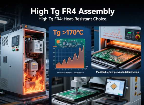
- Tg ≥170°C: Glass transition temperature (Tg) ensures the substrate resists softening under heat. ShwayPCB uses Tg=180°C FR4 for mmWave assemblies, preventing warpage during reflow soldering (240°C peak) and in-field operation.
Selecting the right FR4 for mmWave requires aligning material properties with application requirements. Below is a step-by-step framework, with examples from ShwayPCB’s
FR4 PCB Assembly solutions:
- Low mmWave (30–60 GHz, e.g., 5G CPE): Prioritize cost with Dk=3.8±0.1, Df≤0.004. 推荐材料: Isola 370HR.
- Mid mmWave (60–100 GHz, e.g., automotive radar): Balance performance and cost with Dk=3.6±0.1, Df≤0.0038, thermal conductivity ≥1.0 W/mK. 推荐材料: Taiyo TC-350.
- High mmWave (100–150 GHz, e.g., short-range aerospace communication): Maximize performance with Dk=3.5±0.08, Df≤0.0035, Tg≥180°C. 推荐材料: Shengyi S1141.
- Outdoor/Automotive: Choose FR4 with moisture resistance (water absorption ≤0.15% per IPC-4101) and UV stability (e.g., Isola 370HR with UV-resistant coating).
- Indoor (e.g., data center mmWave links): Standard mmWave FR4 (e.g., Taiyo TC-350) suffices, as moisture and temperature variation are minimal.
- Fine-Pitch Components (0.3mm BGAs): Select FR4 with low coefficient of thermal expansion (CTE: 12–14 ppm/°C) to avoid solder joint cracking during thermal cycling.
- Low-Volume Prototyping: Use readily available mmWave FR4 (e.g., Isola 370HR) to minimize lead times for Low-Volume PCB Assembly. ShwayPCB stocks these materials, enabling 3–5 day turnaround for 1–10 unit mmWave prototypes.
A client developing automotive ADAS radar needed a cost-effective mmWave solution. ShwayPCB recommended Taiyo TC-350 FR4 (Dk=3.6±0.1, Df=0.0038 at 77 GHz) paired with:
- 2oz copper traces (70μm) for controlled impedance (50Ω ±3%).
- ENIG surface finish to maintain solderability after 1,000 thermal cycles (-40°C to +125°C).
- Turnkey FR4 PCB Assembly (sourcing, SMT, X-ray testing) for 20-unit low-volume production. The assembly achieved insertion loss <0.5dB/cm at 77 GHz—meeting the client’s performance targets at 40% lower cost than PTFE-based alternatives.
MmWave projects—especially in automotive, 5G, and aerospace—rely on rapid prototyping to validate design choices (e.g., antenna layout, component placement) before scaling. Low-Volume PCB Assembly for FR4 mmWave offers three critical advantages:
Engineers often need to test multiple FR4 variants (e.g., Isola 370HR vs. Shengyi S1141) to optimize performance. Low-volume assembly enables:
- 3–5 day turnaround for 1–5 unit batches of each material.
- Flexibility to modify trace widths or component footprints between batches (e.g., adjusting a radar antenna trace from 0.1mm to 0.12mm to reduce loss).
- ShwayPCB Example: A 5G startup tested 3 FR4 materials in 10-unit low-volume batches over 2 weeks, identifying Shengyi S1141 as the optimal choice for their 60 GHz CPE device—cutting development time by 60% vs. high-volume prototyping.
MmWave FR4 assemblies include high-cost features (e.g., controlled impedance traces, thermal vias) that are risky to scale without validation. Low-volume assembly:
- Reduces upfront investment (e.g., $500–$1,000 for 10 units vs. $5k–$10k for 100 units).
- Enables comprehensive testing (e.g., TDR for impedance, insertion loss measurement) on a small sample before committing to high-volume.
Niche mmWave projects (e.g., medical mmWave imaging, industrial level sensors) require custom designs that high-volume assembly lines cannot support. Custom FR4 PCB Assembly for low-volume runs:
- Accommodates non-standard components (e.g., high-power mmWave amplifiers, custom antennas).
- Integrates application-specific testing (e.g., radiation pattern measurement for radar antennas).
- ShwayPCB Example: A medical device company needed 15 custom FR4 mmWave assemblies for a breast imaging prototype. Low-volume assembly allowed integration of a rare 60 GHz transceiver and custom antenna array, with functional testing to validate imaging resolution—all delivered in 7 days.
Yes—for 60% of mmWave use cases (30–100 GHz, low-to-mid power). PTFE (e.g., Rogers 4350B) offers lower Df (0.003 vs. 0.0035 for mmWave FR4) but costs 2–3x more. FR4 is ideal for cost-sensitive apps like 5G CPE, automotive radar, and indoor mmWave links. For ultra-high-performance (100+ GHz, aerospace), PTFE remains preferable.
Optimized FR4 (e.g., Shengyi S1141) maintains reliable performance up to 150 GHz, with insertion loss <0.8dB/cm at 150 GHz. Beyond 150 GHz, signal loss becomes prohibitive for most applications—PTFE or ceramic substrates are recommended here.
Key differences include:
- Material Inspection: Testing Dk/Df at target frequency (e.g., 77 GHz) for each FR4 batch.
- Impedance Control: Laser-based trace width measurement (±0.005mm) to ensure 50Ω ±3% tolerance.
- Solder Paste: Type 5 solder paste (20–38μm particles) for fine-pitch mmWave components (0.3mm BGAs).
- Testing: TDR for impedance, vector network analyzer (VNA) for insertion loss, and X-ray for BGA solder joint voids (<5%).
ShwayPCB’s Low-Volume PCB Assembly for mmWave FR4 offers:
- 1–5 units: 3–4 days (expedited).
- 6–20 units: 5–7 days.
- 21–100 units: 7–10 days.
Lead times are shorter than PTFE assembly (which requires specialized processing), as FR4 uses standard manufacturing equipment.
- IPC-610 Class 3 (high-reliability electronics).
- IATF 16949 (automotive mmWave).
- ISO 13485 (medical mmWave).
- MIL-STD-883H (aerospace mmWave).
All assemblies include certification of Dk/Df testing and impedance validation.
Optimized FR4 PCB Assembly is a cost-effective, high-performance solution for most millimeter-wave applications—from 5G to automotive radar—when paired with the right high-frequency FR4 materials. By prioritizing dielectric stability (Dk), low loss (Df), and thermal conductivity, engineers can achieve mmWave performance that rivals specialized substrates at a fraction of the cost. Low-Volume PCB Assembly further accelerates mmWave development, enabling fast iteration, cost-effective validation, and customization for niche projects.
ShwayPCB’s
FR4 PCB Assembly solutions are tailored to mmWave’s unique demands, from material sourcing (stocked mmWave FR4 variants) to precision assembly (VNA testing, X-ray inspection) and low-volume prototyping. Our team of high-frequency experts provides end-to-end support—from material selection to functional testing—ensuring your mmWave FR4 assembly meets performance and reliability targets.
To discuss your mmWave FR4 project, request a Dk/Df material sample, or get a customized quote for
Low-Volume PCB Assembly, contact ShwayPCB at
yuan@shwaypcb.com. For detailed specs on our mmWave FR4 materials and testing protocols, visit our dedicated FR4 assembly service page.