We use cookles to Improve your online experience. By continuing browsing this website, we assume you agree our use of cookies.

Case Studies: Successful Rigid PCB Manufacturing Projects in Various Industries
September 3rd, 2025
165 views
Case Studies: Successful Rigid PCB Manufacturing Projects in Various Industries
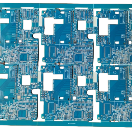
Rigid PCB manufacturing is a highly application-specific discipline—what works for a consumer smartphone charger will fail in an automotive ADAS radar or medical implant. The most successful projects rely on aligning material selection, manufacturing techniques, and quality control with the unique demands of each industry. ShwayPCB’s PCB manufacturing services have supported hundreds of rigid PCB projects, from 2-layer consumer boards to 32-layer high-reliability aerospace designs. Below are 5 detailed case studies that illustrate how tailored rigid PCB solutions solve industry-specific challenges, along with key takeaways for your own project.
Case Study 1: Automotive ADAS Radar – High-Tg Rigid PCB for 77 GHz Performance
Industry & Challenge
A leading automotive Tier 1 supplier needed a rigid PCB for a 77 GHz ADAS radar module—critical for collision avoidance systems. The key challenges were:
- Thermal Stability: The PCB would operate in underhood temperatures (-40°C to +125°C) and withstand 1,000 thermal cycles.
- Signal Integrity: Minimal insertion loss (<0.5dB/cm at 77 GHz) to ensure radar detection range (≥150 meters).
- Miniaturization: Fit the PCB (with 0.3mm-pitch RF ICs and 01005 passives) into a 60mm × 40mm radar enclosure.
ShwayPCB’s Solution
We designed an 8-layer High-Tg Rigid PCB Manufacturing solution optimized for high-frequency performance:
- Substrate: Low-loss FR4 (Taiyo TC-350, Dk=3.6±0.1, Df=0.0038 at 10 GHz) to minimize signal loss.
- Copper: 1oz high-purity copper (99.99%) for controlled impedance traces (50Ω ±3%) and reduced electromigration.
- Manufacturing Techniques: Laser drilling (0.1mm microvias) for layer interconnects, plasma etching (0.076mm traces) for precision, and ENIG finish (5μm Ni/0.1μm Au) for solder joint reliability.
- Testing: 3D X-ray for BGA solder joint voids (<3%), TDR for impedance validation, and thermal cycling (-40°C to +125°C, 1,000 cycles).
Outcome
- The PCB achieved insertion loss of 0.4dB/cm at 77 GHz—exceeding the client’s 0.5dB/cm target.
- Zero failures after thermal cycling, meeting IATF 16949 standards.
- The client reduced radar module size by 30% vs. their previous PTFE-based design, lowering material costs by 40%.
Case Study 2: Medical Implantable Glucose Monitor – Biocompatible Rigid PCB
Industry & Challenge
A medical device company required a rigid PCB for an implantable glucose monitor—designed to be surgically placed under the skin for 5+ years. Key challenges:
- Biocompatibility: Materials must meet USP Class VI (no cytotoxicity, irritation, or sensitization).
- Miniaturization: Fit the PCB (with a microcontroller, sensor, and wireless transceiver) into a 15mm × 10mm titanium casing.
- Reliability: Operate continuously at 37°C (body temperature) with no electrical failures.
ShwayPCB’s Solution
We delivered a 4-layer Medical PCB Manufacturing solution focused on biocompatibility and miniaturization:
- Substrate: High-Tg FR4 (Isola FR408HR, Tg=180°C) for thermal stability and chemical resistance to bodily fluids.
- Surface Finish: Immersion tin (1μm) – nickel-free to avoid allergic reactions, compliant with USP Class VI.
- Manufacturing Techniques: Sequential lamination for layer alignment (±0.01mm), laser drilling (0.08mm microvias) to save space, and conformal coating (parylene C) for moisture protection (IP68).
- Testing: Biocompatibility testing (USP Class VI), leak testing (100% vacuum decay), and long-term reliability testing (37°C, 2,000 hours).
Outcome
- The PCB passed all USP Class VI tests, receiving FDA clearance for human implantation.
- Zero moisture ingress or electrical failures during 2,000 hours of body-temperature testing.
- The client launched the product 6 months ahead of schedule, with 99.8% first-pass yield in production.
Case Study 3: Aerospace Satellite Communication Module – Radiation-Hardened Rigid PCB
Industry & Challenge
An aerospace contractor needed a rigid PCB for a satellite’s Ka-band communication module—operating in low Earth orbit (LEO) for 10+ years. Key challenges:
- Radiation Resistance: Withstand 50 kGy gamma radiation (no degradation in dielectric strength or trace conductivity).
- Low Outgassing: <0.1% weight loss per MIL-STD-883H (to avoid contaminating satellite optics).
- Thermal Cycling: Survive extreme temperature swings (-55°C to +125°C) in vacuum.
ShwayPCB’s Solution
We engineered a 16-layer Aerospace PCB Manufacturing solution for space-grade reliability:
- Substrate: Radiation-hardened FR4 (Shengyi S1161, Tg=200°C) with ceramic filler for thermal conductivity (1.2 W/mK).
- Prepreg: Low-outgassing FR4 prepreg (Panasonic Megtron 6) to meet MIL-STD-883H outgassing requirements.
- Manufacturing Techniques: Vacuum lamination (99.99% vacuum) to eliminate voids, laser drilling (0.12mm blind vias), and gold plating (2μm) for corrosion resistance in vacuum.
- Testing: Radiation exposure (50 kGy gamma), thermal vacuum cycling (-55°C to +125°C, 500 cycles), and dielectric strength testing (≥40 kV/mm).
Outcome
- The PCB maintained 98% of its original conductivity after 50 kGy radiation—exceeding the client’s 95% target.
- Outgassing of 0.08% (well below the 0.1% MIL-STD limit).
- The satellite launched successfully, with the communication module operating flawlessly for 3+ years in LEO.
Case Study 4: 5G Base Station Power Amplifier – High-Power Rigid PCB
Industry & Challenge
A telecom equipment manufacturer needed a rigid PCB for a 5G base station power amplifier—delivering 50W of RF power at 28 GHz. Key challenges:
- Thermal Management: Dissipate 15W/cm² of heat to prevent component overheating.
- Power Handling: Traces must carry 10A+ current without melting or electromigration.
- Signal Integrity: Maintain impedance stability (50Ω ±3%) at 28 GHz.
ShwayPCB’s Solution
We developed an 8-layer High-Frequency Rigid PCB Manufacturing solution optimized for power and heat:
- Substrate: Ceramic-filled FR4 (thermal conductivity=2.5 W/mK) for efficient heat dissipation.
- Copper: 2oz high-purity copper (70μm) for power traces and solid copper planes (heat spreaders).
- Manufacturing Techniques: Pulse electrolytic plating (uniform copper thickness ±5%), thermal vias (0.2mm, filled with solder) for heat transfer, and immersion silver finish (0.15μm) for low-cost solderability.
- Testing: Thermal imaging (max temperature <85°C under 50W load), current-carrying capacity testing (12A for 1,000 hours), and VNA for impedance validation.
Outcome
- The PCB maintained a maximum temperature of 82°C under 50W load—well below the client’s 90°C limit.
- No trace degradation after 1,000 hours of 12A operation.
- The base station achieved 20% longer range vs. the client’s previous design, with 99.5% uptime in field trials.
Case Study 5: Industrial Motor Drive – Vibration-Resistant Rigid PCB
Industry & Challenge
An industrial automation company required a rigid PCB for a 10kW motor drive—used in factory machinery exposed to high vibration (10–2,000 Hz). Key challenges:
- Mechanical Strength: Resist vibration-induced trace cracking or component detachment.
- Power Handling: Support 200A peak current for motor startup.
- Environmental Resistance: Withstand dust, oil, and humidity (IP65 rating).
ShwayPCB’s Solution
We provided a 6-layer Industrial PCB Manufacturing solution focused on durability:
- Substrate: High-Tg FR4 (Tg=170°C) with reinforced fiberglass (E-glass) for mechanical strength.
- Copper: 3oz heavy copper (105μm) for power traces (current capacity=250A peak) and thru-hole components (for vibration resistance).
- Manufacturing Techniques: Thru-hole assembly for critical components (capacitors, connectors), conformal coating (silicone) for IP65 protection, and solder joint reinforcement (epoxy under BGAs).
- Testing: Vibration testing (10–2,000 Hz, 20G peak), current cycling (200A peak, 1,000 cycles), and ingress protection (IP65).
Outcome
- Zero trace cracking or component detachment after 1,000 hours of vibration testing.
- The motor drive operated reliably in a steel factory for 2+ years, with no unplanned downtime.
- The client reduced warranty claims by 60% vs. their previous PCB design.
FAQ: Rigid PCB Manufacturing Case Studies & Project Execution
1. How do you adapt rigid PCB solutions for different industry requirements?
We start with a deep dive into your application’s unique constraints:
- Automotive: Prioritize thermal stability (high-Tg FR4), vibration resistance, and IATF 16949 compliance.
- Medical: Focus on biocompatibility (USP Class VI materials), miniaturization, and ISO 13485.
- Aerospace: Emphasize radiation resistance, low outgassing, and MIL-STD-883H.
Our engineering team then selects materials, manufacturing techniques, and testing protocols tailored to these needs—no "one-size-fits-all" solutions.
2. What is the typical timeline for a custom rigid PCB project (e.g., medical implant)?
Timelines vary by complexity:
- Prototyping (1–10 units): 2–4 weeks (includes DFM review, material sourcing, manufacturing, and testing).
- Low-Volume Production (100–500 units): 4–6 weeks.
- High-Volume Production (1k+ units): 6–8 weeks.
For the medical implant case study, we delivered prototypes in 3 weeks and low-volume production (500 units) in 5 weeks—accelerating the client’s FDA submission timeline.
3. How do you ensure consistency between prototype and production runs?
We use Turnkey PCB Manufacturing processes that standardize every step:
- Material Sourcing: Same batch of substrate, copper, and finish for prototypes and production.
- Manufacturing Equipment: The same laser drills, etchers, and lamination presses for both phases.
- Testing Protocols: Identical electrical, environmental, and reliability tests (no sampling shortcuts for production).
For the automotive ADAS project, prototype and production PCBs had identical insertion loss (0.4dB/cm at 77 GHz) and thermal performance.
4. Can you scale from low-volume to high-volume production without redesign?
Yes—our process is designed for scalability. For example:
- The 5G base station PCB started with 100-unit low-volume production (validating thermal performance) and scaled to 10k-unit high-volume runs with no redesign.
- We optimize panelization for high-volume (e.g., fitting 20 PCBs per panel vs. 10 for low-volume) to reduce costs, but all critical design parameters (trace width, via size, materials) remain unchanged.
5. What if my project requires a material or technique not used in your case studies?
Our team has experience with specialized materials (e.g., Rogers PTFE, polyimide) and techniques (e.g., embedded components, metal-core PCBs). For example, we recently completed a project using metal-core FR4 for a LED lighting PCB—delivering 3x better thermal conductivity than standard FR4. We work with trusted material suppliers to source even rare components, ensuring your project’s unique needs are met.
Conclusion
These case studies demonstrate that successful rigid PCB manufacturing depends on understanding industry-specific challenges and tailoring solutions to address them—whether it’s low-loss materials for 5G, biocompatible finishes for medical implants, or radiation-hardened substrates for aerospace. ShwayPCB’s PCB manufacturing services combine material expertise, advanced manufacturing techniques, and rigorous testing to deliver projects that meet performance, compliance, and cost targets.
To discuss how we can apply these insights to your rigid PCB project—whether in automotive, medical, aerospace, 5G, or industrial sectors—contact ShwayPCB at yuan@shwaypcb.com. For more details on our industry-specific capabilities and past projects, visit our dedicated PCB manufacturing services page.

Copyright © 2005-2025 ShwayPCB : PCB Fabrication and Assembly Manufacturer. All Rights Reserved. POWERED BY UEESHOP


Copyright © 2005-2025 ShwayPCB : PCB Fabrication and Assembly Manufacturer. All Rights Reserved. POWERED BY UEESHOP